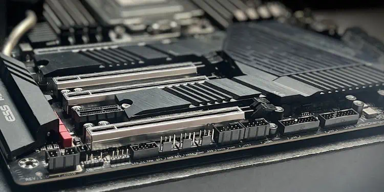
Every hardware component requires some form of motherboard connection. External I/O devices can be plugged into their respective ports, which is pretty straightforward.
But when it comes to internal components, you’ll need to access the mainboard and plug the cables into their relevant headers or female connectors. Some of these are meant to power your devices, while others act as an interface for data transmission.
The ATX Main and 12V connectors power the entire board. Similarly, you can find relevant headers for cooling fans, water pumps, and RGB strips. Even users with SATA drives need to utilize the available data ports.
Besides internal components, the add-on cards and the front panel ports/buttons also require a motherboard connection.
Well, understanding the functions of all these headers is vital, especially for first-time PC builders. This detailed guide should give you an overview of all the connectors available on most motherboards.
Power Connector
Let’s begin with the connectors that power the motherboard. They have a direct connection with the power supply unit, and without them, your system won’t boot.
Among the five PSU cables, only two require direct connection to the mainboard – the main ATX and the 12V CPU ATX. Don’t worry! I’ve covered them both:
ATX Main Power
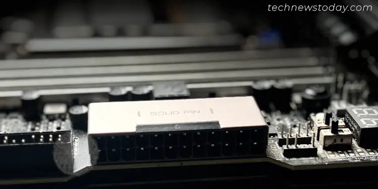
Most motherboards today incorporate the standard 24-pin ATX power connector (very old ones could come with a 20-pin). It’s usually located somewhere between the top and the middle right.
Look for ATXPWR1, EATXPWR, ATX, or similar labels on the PCB. Also, note that some boards mount them on the side, which may confuse you. The above image of the AORUS TRX40 MASTER should give you a much clearer idea.
Generally, the main power plugs are labeled P1 or ATX and have a 20+4 pin configuration. Meaning that you can split them into two. It’s there to ensure compatibility with the older boards having a 20-pin configuration.
Before connecting the relevant cable, check the tab/clip to secure it. And if you have to unplug it, make sure you hold onto the clip before pulling it out.
ATX 12V
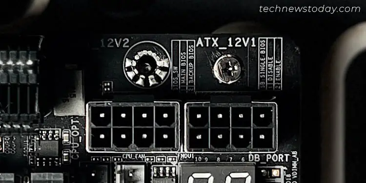
Unlike the ATX power connector (where most motherboards use 24 pins), CPU or ATX 12V can come in 4-pin, 8-pin, or even a combination of both!
Lower-end boards come with a single 4-pin CPU connector, which should generally be enough. But if you have a mid/high or even budget board (usually in the newer ones), you’ll find one of these – a single 8-pin, one 8-pin one 4-pin, or two 8-pins.
Take the P4 or ATX 12V cable (which can be split) and insert it into the dedicated header. Check for these labels to be super sure – CPU_PWR1, ATX_12V, EATX12V, etc.
As with the main power connector, they also come with a tab to ensure you do not make any mistake with the orientation. Also, it’s much easier to insert and requires very little force in comparison to the former.
MOLEX
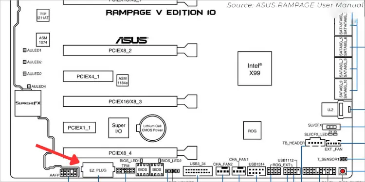
MOLEX connectors are normally used for powering floppy drives, fans, CD drives, etc. However, some higher-end motherboards include them for additional power support.
It’s always a good idea to check for such exceptions, as newer boards might come with additional features that might be something new to hear about.
For instance, ASUS RAMPAGE V (10th edition) comes with a MOLEX connector (labeled EZ_PLUG). It’s meant to provide additional power when using multiple graphics cards.
If you’re building a high-end rig, it’s essential to choose an appropriate PSU that meets your power demands for system stability.
Usually, motherboards with (8+4) pin CPU and additional MOLEX connectors seek high wattages. That’s the reason most manufacturers recommend getting a PSU that supports the latest ATX12V specifications.
Connectors for Storage Drives
Modern motherboards come with M.2 sockets that support the newer NVMe SSDs. They are directly attached to the circuit board and do not require any cable connection.
But if you sport an older model or you’re still utilizing SATA or older PATA storage drives, they need to be connected to a standard bus interface. Let’s look into them in a little more detail.
SATA Ports
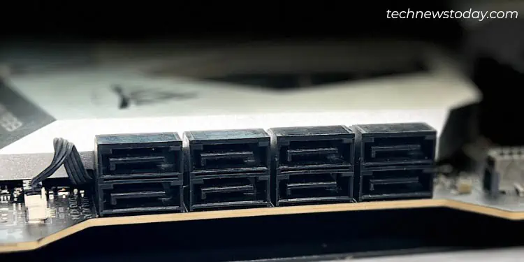
Every modern board comes with 6 to 8 SATA ports. While you may opt for anyone, there’s an exception. If you have attached an NVMe SSD on the M.2 socket already, some SATA ports get disabled.
Also, note that the ports I’m referring to here are for data – those having an ‘L’ shape. Your SATA drives also need a direct PSU connection. For that, you need to connect the dedicated power cable.
SATA ports/connections can be found soldered on the mainboard itself or grouped together somewhere between the middle and bottom-right corners. Each of them is assigned a dedicated number which can be identified from the label imprinted on the PCB.
Moving on, the SATA ports can also be of different revisions. While most boards today support SATA III, older models could integrate the earlier versions I and II Here are their basic differences you should know:
| SATA Version | Data Transfer Rate |
| I | 1.5 Gb/s |
| II | 3.0 Gb/s |
| III | 6.0 Gb/s |
Although SATA ports are backward compatible, they will only achieve the speed of the lower interface. This means that if you connect a SATA II drive to a SATA III port, it is only capable of running at 3 Gb/s.
Even the SATA versions have different revisions. To ensure the dedicated ports support the features you’re looking for (like NCQ, AHCI, different RAID levels, NVMe SSD support, hot plugging, etc.), I advise checking your motherboard’s specifications.
IDE / PATA Connectors
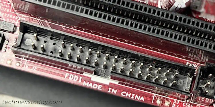
IDE/PATA hard drives are a thing of the past and hardly anyone uses them. But before SATA became a standard, most motherboards used PATA.
As shown in the above figure, my old MSI MS-7529 motherboard supports an FDD1 header for connecting PATA storage drives.
If you can recall, they use the 40-pin ribbon cable for data that can offer a maximum of 133 MB/s transfer speed. To power the PATA drives, you’ll require a MOLEX connector.
Fan Connectors
To ensure your PC remains cool at all times, it’s essential that your fans run at optimal RPMs. Having said that, every installed fan needs to have a motherboard connection.
But there are a plethora of fan connectors that might be baffling, especially for beginners. Also, older boards come with 3 pins while most newer ones have 4-pin configurations.
These are for two fan types – PWM (Pulse Width Modulation) and DC (Direct Current). Their main difference is the fourth pin which offers better duty cycle control and quieter operation.
You can still connect a 3-pin to a 4-pin motherboard connector and vice versa. However, your fans will only operate in DC mode this way.
While you’re at it, keep your eyes on its orientation. In most boards, there’s a tab to help you out. But if you can’t find one, make sure the black wire matches the ground pin.
Without getting into further technical details, let’s come back to the main topic of discussion. Here, I will guide you through the different fan connectors along with each of their purpose.
CPU Fan
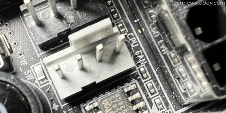
This header is located near the CPU socket and is usually labeled CPU_FAN. You have probably guessed it – yes, it is for the cooler that seats right above the processor.
While most motherboards are rated to support CPU fan power of 12 W (1 A), it’s still a good idea to verify this on your user manual.
Since CPU fans are one of the most essential components, you need to have at least one cooler connected in the relevant header at all times. Otherwise, you’ll meet with some form of CPU Fan error.
What about radiator fans on AIOs or custom loops? You should go for CPU_FAN for them as well. And if these coolers embed multiple fans, you’ll need optional headers, which is what I’m going to cover next.
Optional CPU Fan
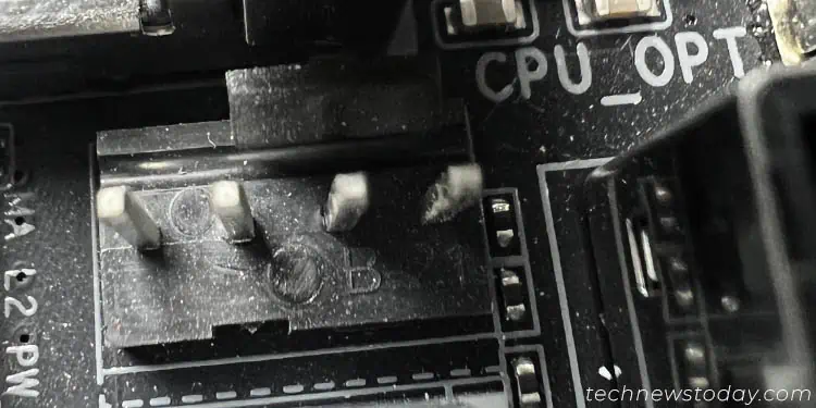
Usually, there’s only one CPU fan header on most motherboards. But if you find CPU_OPT, CPU_FAN2, or similar indications, these are for additional cooling fans. Opt for them especially when using radiators or twin-tower heatsinks.
The general idea is to go for the CPU_FAN and if there exist any other fans that require the same connection, use the optional header.
Chassis/Case/System Fan
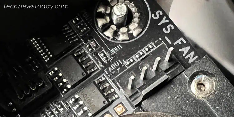
Depending on the motherboard model, you can find one of these fan headers – CHA_FAN, SYS_FAN, etc. These are all for your case fans that help provide a better environment.
Since users go for multiple fans (on the top/right/rear/front), most manufacturers meet this demand and offer anywhere from two to six relevant headers. There’s no rule as to which one you should choose – anyone will work fine!
AIO/Water Pump
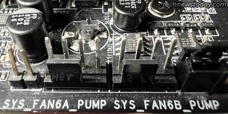
While I did mention that the radiators need to be connected to the CPU_FAN connector, what about the pump? Well, most boards that are specialized for water cooling offer these dedicated headers– AIO_PUMP, B_PUMP, and WP.
However, not all motherboards support such headers. In such cases, even the CPU_FAN header should do the job. In fact, some AIOs come with a combo of 3/4-pin (for radiator fan speed based on CPU temperature), SATA (for powering the pump), and USB (for RGB features).
So, it’s better to check your motherboard manual before proceeding. When our team was setting up a custom water-cooling loop on ASRock X570 AQUA, it offered the same headers for water cooling pumps as well as chassis and CPU fans.
Important Tip: There’s no universal motherboard connector for your coolers. While I’ve already explained the general idea in detail, it’s always better to check your motherboard manual before proceeding. Each system’s configuration might be a little different, especially when you’re setting up AIO or custom water cooling.
RGB / ARGB LED Headers
While we are on the topic of fans, I do not want to miss out on its aesthetic RGB lighting feature. If you own an RGB fan, you’re likely going to get two cables. One provides power and speed customization while the other is for supporting the LEDs.
Apart from the cooling fans, these headers can also be used for RGB LED strips. But since motherboards only offer one or two ports, they might not satisfy your needs.
While such products usually come with a controller, you may even purchase one if it doesn’t. With this, you don’t need to connect the LED cable to the relevant header. They are rather powered by the SATA or MOLEX connector. So, no worries even if your motherboard doesn’t have an RGB header.
But if you’re looking to attach an RGB fan or LED strip to the respective connector, there are two more things to consider. Does your device support RBG or ARGB lighting? Based on your answer, you need to pick the appropriate motherboard header.
Addressable LED
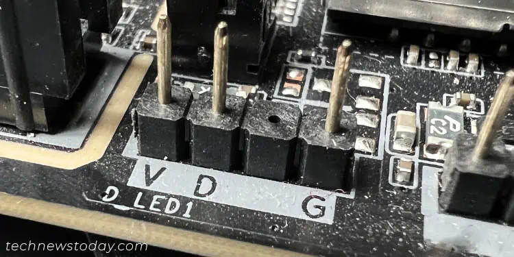
If your fans or LED strips support ARGB, connect them to the Addressable LED headers. Look for ADDR_LED, JRAINBOW, D_LED, or similar indications on the PCB (best to refer to the motherboard manual).
Although they have a 4-pin configuration, the 3rd one remains empty. So, technically, it’s a 3-pin configuration that supports LED strips of power rating 15W (5V and 3A). When setting this up, make sure you match the arrow/triangle mark to the first pin (which is for +5V).
Caution: Never connect the strips or ARGB fans on an incorrect header. Due to voltage mismatch, the LEDs might get damaged and won’t light up by any chance.
Non-Addressable LED
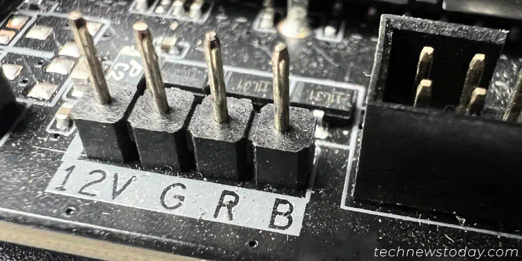
While ARGB devices support the customization of each LED individually (at the same time), the standard RGB ones don’t. The former is available on newer and high-end boards only, which is why the static RGB headers are still considered the ‘standard’.
They have a 4-pin configuration that can power both regular LED strips and RGB fans of a maximum +12V load (3A, 36W). Look for RGB_LED, LED_C1/C2, JRGB, RGB_HEADER, or similar labels.
Even though these connectors are compatible with both fans and LED strips, some exclusive motherboards offer a dedicated one just for the fans. For instance, ASRock X570 AQUA comes with AMD_FAN_LED. Usually, the strips also work fine when connected but it’s better to connect the RGB fans here.
Front Panel Connectors
The ports, LEDs, and buttons on the front of your chassis also require some form of motherboard connection. However, the exact header differs and it’s essential to know the right one. Let’s jump right into them.
System Panel Header
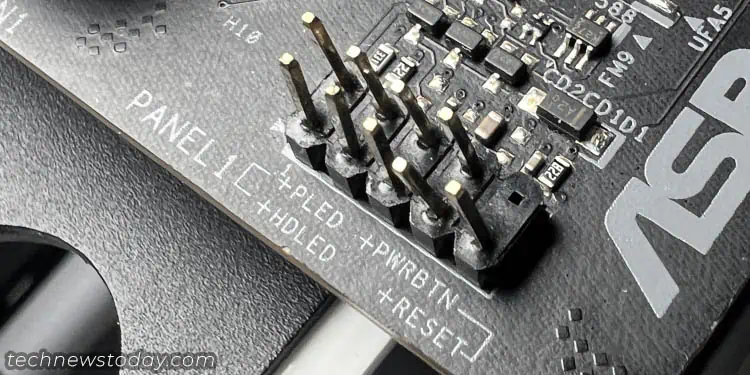
Amongst all, connecting the system panel to the motherboard is the most important thing to do. In this header/connector, you need to attach your system’s power switch, reset button, power LED, and hard drive activity LED.
Look for PANEL, F_PANEL, JFP1, or a somewhat identical label on the PCB. Then, take each plug that comes with the case (should have the dedicated label) and connect it as stated in the manual.
Additionally, a few motherboard models include speaker and chassis intrusion in the same header itself. Others might provide two different connectors. For instance, ASRock AQUA X570 offers SPK_PLED1 for Power LED/speaker and PANEL1 for the standard ones (as pictured above).
Unlike other headers, these are completely optional. When testing different motherboards on the Test Bench, we usually connect only the POWERBTN plug (from the external power button switch). This prevents us from manually shorting the pins to kick-start the system.
USB Headers
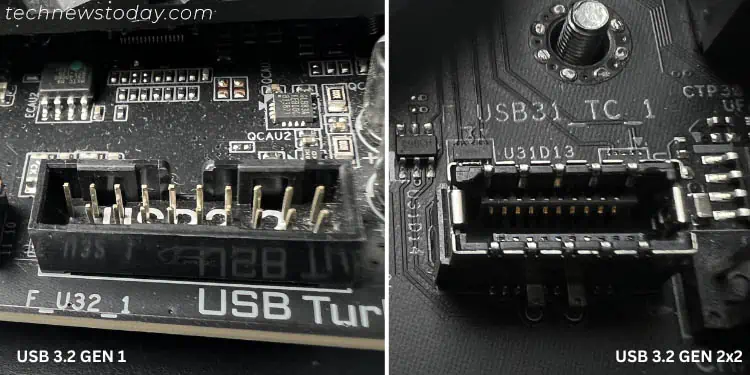
While the system panel connectors are for the power buttons, these headers are for your extra USB ports. Your case includes a separate cable for the USB modules and each header can support one to two Type-A or C ports.
For that reason, every motherboard comes with an abundant number of USB headers. Some even include multiple generations. Thus, it’s essential to plug in the module cable to the appropriate connector.
The labels vary based on the manufacturer. It could be F_USB, J_USB, F_PANEL_USB, USB_1_2, USB_3_9_10, or anything that’s similar to these.
The below table should assist you with the general specifications of all the USB headers. Note that your motherboard supports just a few generations mentioned here. Most have 2.0 and 3.0/3.1 but some even offer 3.2 that supports Type-C.
| USB Header Generation | Maximum Supported Speed | Supported Ports |
| 1.1 – 2.0 | 480 Mbps | Type-A |
| 3.0 | 5 Gbps | Type-A |
| 3.1 (Gen 1 & 2) | 10 Gbps | Type-A |
| 3.2 (Gen 1×1, 1×2, 2×1) | 10 Gbps | Type-A, Type-C |
| 3.2 (Gen 2×2) | 20 Gbps | Type-C |
Audio Headers
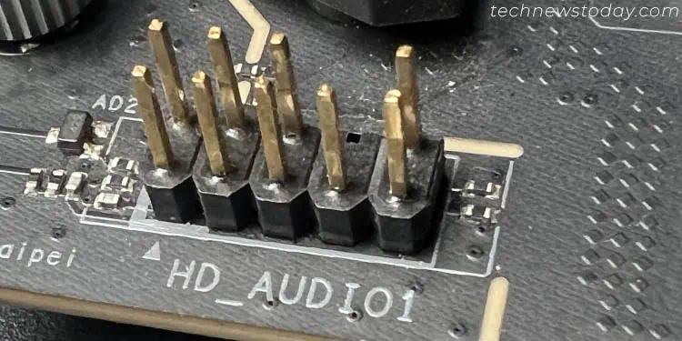
Popularly known as AAFP (Analog Audio Front Panel Headers), it allows your case’s microphone and headphone ports to function. This way, you do not need to choose the motherboard audio ports, which is a little hard to reach (especially if your device has a smaller length).
In most boards, it has a 10-1 pin configuration and usually, there’s only one header available. It’s easy to locate as it comes next to the other front panel headers, generally in the bottom section of the motherboard. Look for these indications – AAFP, HD_AUDIO1, F_AUDIO, JAUD1, etc.
Today, modern cases with HD Audio cables but if you rock an older one, it may feature an AC’97 cable. Make sure you connect the right one or the audio ports might not work.
A few models also comprise a digital audio connector. It allows you to attach a S/PDIF module that usually supports two or more coaxial/optical sound ports. Check for the SPDIF_OUT header on your manual to verify this.
Thunderbolt Header
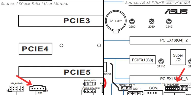
After installing an add-on Thunderbolt I/O card, the next thing to do is connect it to the relevant header via a GPIO cable. Do note that the pin configuration can vary depending on the motherboard model.
As you can see in the user manual screenshots above, ASUS PRIME Z790-V WIFI includes a ‘TB_HEADER’ with 13 pins. On the other hand, ASRock X570 Taichi embeds a ‘TB1’ header with a 5-pin configuration.
Only high-end motherboards support Thunderbolt ports and only a few ones integrate a dedicated header for AICs. So, before purchasing one, I highly recommend inspecting the specs to confirm if your mainboard supports Thunderbolt headers.
Clear CMOS Header
During most hardware troubleshooting, clearing CMOS can be an effective solution. Whether your PC isn’t booting up or you need to restore BIOS to factory defaults, most manufacturers recommend shorting the CMOS header. Doing so resets the RTC RAM that stores the system’s time, date, and other parameters.
However, the process varies slightly based on the number of pins available on your mainboard. I’ve covered them both in brief below.
Important: Make sure to properly shut down the system and unplug the PSU cord before shorting the relevant pins.
2-pin
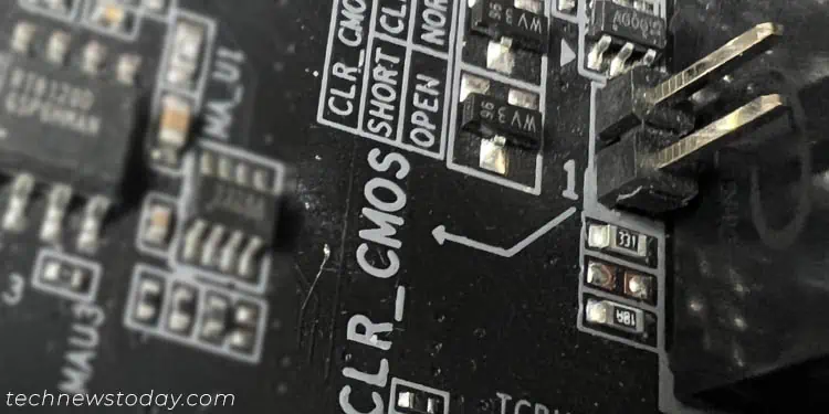
Most modern motherboards include a 2-pin RTC header. To clear CMOS, you can place a jumper cap (if available) or simply short them for a few seconds using a flat-headed screwdriver.
3-pin
If you have a relatively older board, it might come with a 3-pin Clear CMOS header.
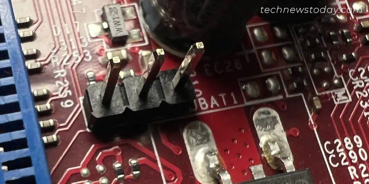
To erase its data, simply change the jumper cap position from the first two pins to the next two. Wait for a few seconds before reverting the configuration.
Miscellaneous
Although I’ve covered the most used connectors and headers, there are still a few more to explore. Here’s a list of some common ones available on most motherboards but these are still rarely used.
Serial and Parallel Port Connectors
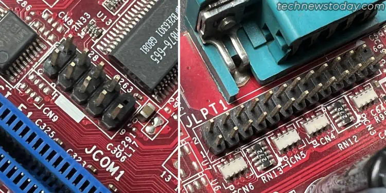
These days, motherboards do not offer older computer ports like COM and LPT on the rear I/O panel. Instead, they come with serial and parallel headers where you can attach the dedicated cables of your add-on card.
Temperature Sensor Header
For users who wish to integrate a thermal sensor for detecting the temperature of various hardware components, some motherboards come with a relevant header.
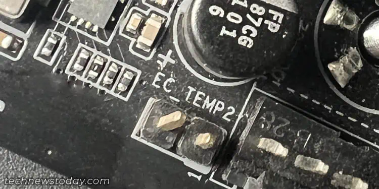
To locate it, look for EC_TEMP, T_SENSOR, or similar labels imprinted on the PCB. They have a 2-pin configuration (SENSOR IN/GND) and are mainly used for checking CPU / discrete GPU / motherboard temperature.
TPM Module Connector
With the popularity of firmware TPM (fTPM), hardware TPM isn’t the primary choice among most users. However, from a security point of view, they are still miles ahead of the former.
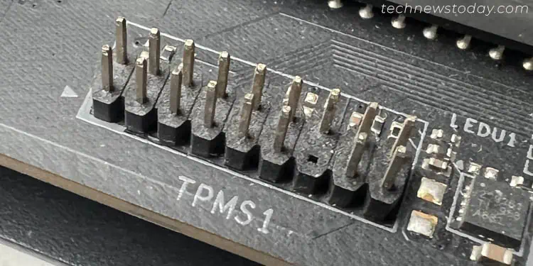
Although dedicated TPM chips come pre-built in some motherboards, others simply offer a dedicated header to add one. Generally, it’s labeled TPM or SPI TPM – so, you shouldn’t have difficulty locating this connector.
Noise Detection Header
Well, loud fans and coolers are always headaches. With the noise detection feature on some high-end motherboards, you can detect the sound pressure in decibels.
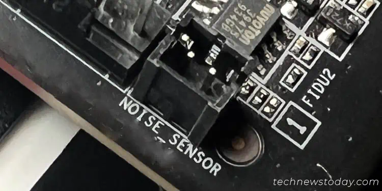
Usually, such models offer at least one noise detection cable, which can be connected directly to the NOISE_SENSOR header. Then, use the BIOS utility or OEM software to read the parameters and you can configure the fan speeds accordingly.
Other Connectors
Even though I have covered most of the connectors available on both old and modern motherboards, I still may have missed out on proprietary ones. So, it’s always recommended to go through the user manual to learn if there’s a new one available.
For instance, our Gigabyte AORUS TRX40 MASTER comes with an Add-in Card Connector. Likewise, MSI MAG 550M MORTAR includes a JCI1 header for chassis intrusion (with a dedicated switch).

