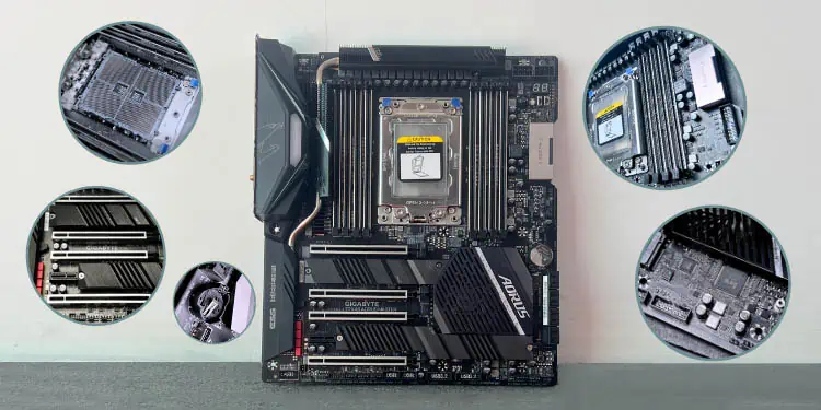
For external peripherals, you need to attach the relevant cables to their respective motherboard ports. Even the PSU, fans, and front panels require motherboard connection through dedicated headers.
However, the most basic internal components (like CPU and RAM) are directly mounted/slotted onto the mainboard. They do not require any cable connection and rather need to be secured using latches, screws, or retaining arms.
The most essential one is the CPU socket, which holds your processor. The installation varies slightly depending on whether you own an Intel or AMD board. Right next to it lies a number of DIMM slots, where your RAM modules can be seated.
Also, there are expansion slots that hold the GPUs, SSDs, Wi-Fi, RAID, and other add-on cards. Today, most motherboards embed PCIe and M.2. While these are considered the standards, there are some legacy ones as well.
In this guide, I will be covering all the slots/sockets on motherboards. This should help you better understand their functionalities and use cases.
Note: The terms ‘slot’ and ‘socket’ have different meanings. Nonetheless, most manufacturers use them interchangeably. For instance, in most ASRock user manuals, M.2 is referred to as a ‘socket’ while MSI nomenclates them as a ‘slot’. Likewise, ‘CPU socket’ and ‘CPU Slot’ are both correct.
CPU Socket / Slot
The brain of your computer – the CPU isn’t soldered onto the PCB. That being said, you’ll have to install it manually, keeping in mind the appropriate alignment. This varies based on the socket type, which is different for Intel and AMD.
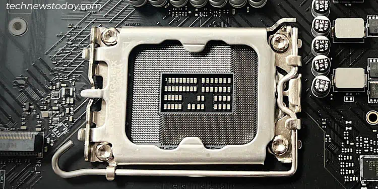
Modern Intel processors use the LGA (Land Grid Array) configuration. Meaning, you’ll find pins on the motherboard’s CPU socket and electric contact pads on the bottom surface of the processor.
On the other hand, most AMD processors use the Pin Grid Array (PGA) packaging. This means the pins are embedded at the bottom surface while the motherboard sockets contain tiny holes.
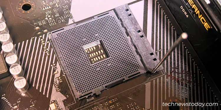
However, there are still exceptions. AMD socket variants (F, C32, G34, SP3, TR4, sTRX4, and AM5) utilize LGA surface-mount packaging. Likewise, some older Intel ones with the naming convention in ‘Socket’ used PGA (like Socket 370, Socket 423, Socket 495, etc.).
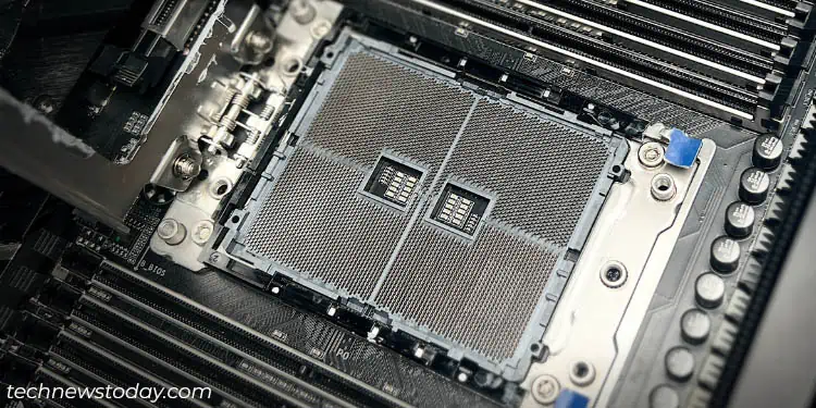
Apart from LGA and PGA, legacy motherboards even came with DIP, PLCC, and edge connector/slot packaging. However, these have gone obsolete and shouldn’t be of much concern for modern-day desktops.
If you have ever examined the specifications, you’ve likely come across different socket names. For Team Blue, there’s a certain number after ‘LGA’, which basically signifies the number of pins. For instance, LGA 1700 means there are a total of 1700 pins on the CPU socket.
But if you’re on Team Red, the sockets will have the following indications – AM3, AM4, AM5, TR4, sTRX4, etc.
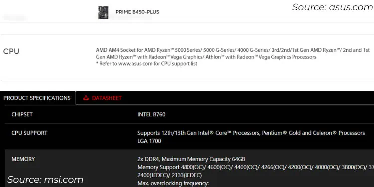
These socket types tell you whether the CPU generation is compatible with the motherboard. For instance, LGA 1700 supports Alder Lake and Raptor Lake processors. So, trying any other CPU (say, Kaby Lake) will not work.
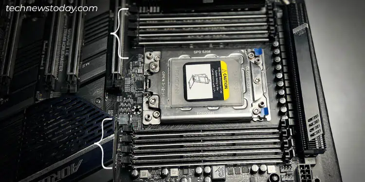
Coming back to installation, the slots often have a retention arm that secures the CPU. Some other boards, like the one illustrated below (Gigabyte AORUS TRX40 MASTER), might have a metal load plate with multiple screws.
The general idea is to mount the processor and pull the retention arm or screw them tightly. Make sure you do not apply any pressure or you may bend the pins. In the end, don’t forget to install a cooler or the CPU will overheat.
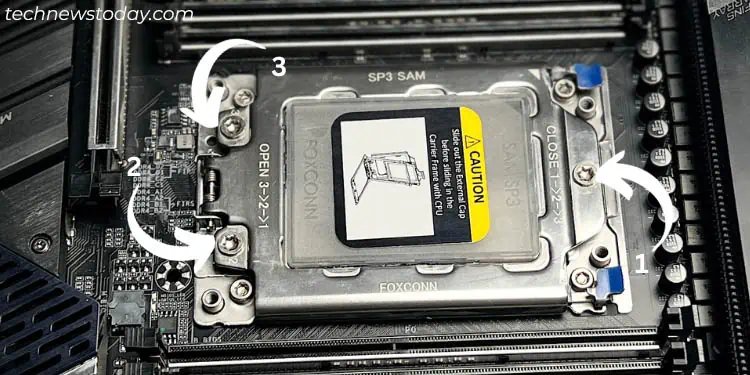
Since the exact steps vary on every motherboard, I highly recommend inspecting the manual before proceeding.
Although motherboards with dual processor sockets exist, they are only intended for high-end servers and workstations. So, in most consumer-based models, you’ll encounter just one CPU socket.
DIMM or Memory Slots
These are the slots for your RAM modules and are located next to the CPU socket. Modern boards come with four slots, but higher-ends can come with 8 or even more!
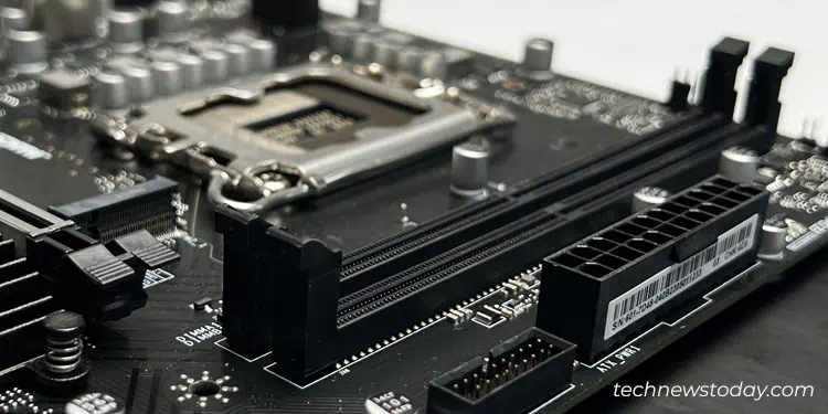
Well, this can differ based on the motherboard factor. For instance, a lot of mid-end mini-ITX and micro-ATX boards come with just two, as demonstrated above.
While you can utilize any one of the DIMM slots, I would suggest going for the one that’s furthest from the processor. This will offer extra headroom if you plan on installing bulky coolers.
But if you’re planning to use two RAM sticks, it’s essential to pick the alternative slots. Along with that, it’s recommended to go for memory modules of the same version (of the same brand) for better compatibility and optimal performance.
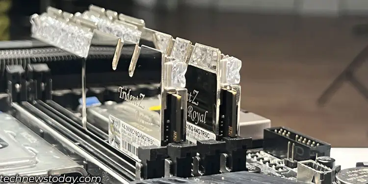
For instance, in a dual-channel configuration, seat the first module on the A4 slot and the other one on the A2. This might vary on every board – some boards may ask you to install the sticks on A1 and A3.
While most boards and processors support dual memory channels, quad-channel is only supported on higher-ends. Usually, such boards come with eight or more slots. The same as with our Gigabyte AORUS TRX40 board demonstrated below that comes with four slots on the left and four on the right of the CPU socket.
Moving on, the majority of mid-end and even lower-end boards are equipped with DDR4 SDRAM DIMM slots. But since the release of DDR5 in July 2020, newer high-end boards have started integrating the compatible DIMM slot. Sooner or later, it will replace DDR4 completely.
So, you might wonder whether you’ll be able to use the older stick on the new DDR5 SDRAM DIMM slot. My answer is a straight NO! None of the DDR generations are forward or backward-compatible.
Each version is an improvement of the former in terms of clock speed, data transfer rate, voltage, channel architecture, latency, power management, and more. Here’s a brief overview of the different types of RAM:
| DDR Type | Maximum Clock Speed (Memory + I/O Bus) | Voltage | Status |
| DDR5 | 8000 MHz | 1.1 V | Latest |
| DDR4 | 3200 MHz | 1.2 V | Most Popular |
| DDR3 | 2400 MHz | 1.5 V | Production stopped in 2022 |
| DDR2 | 1066 MHz | 1.8 V | Obsolete |
| DDR1 | 400 MHz | 2.5 V | Obsolete |
The RAM modules only fit in one direction. Spread the retaining clip and check the notch alignment before vertically seating the sticks. You should hear a ‘click’ sound to confirm that you have done this appropriately.
What about ECC and non-ECC RAMs? Well, this completely depends on whether your motherboard and processor support it. If you install buffered/registered ECC modules on a non-ECC system, you’re likely going to encounter boot issues.
PCIe Expansion Slots
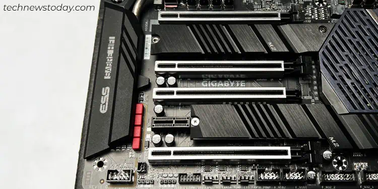
If you’re planning to add a dedicated GPU or some other daughterboards, you’re going to need the PCIe (Peripheral Component Interconnect Express) slots.
Basically, it’s the high-speed expansion bus standard that lets you install sound cards, NIC (Network Interface Controllers), Wi-Fi cards, capture cards, RAID controllers, etc.
Based on size, they are categorized into four types – x1, x4, x8, and x16. These are popularly referred to as PCIe lanes, where the relevant device is connected to the processor or the motherboard’s chipset through two copper wires on the PCB. The data travels here bidirectionaly.
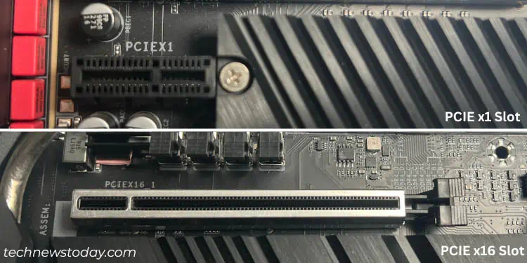
Generally, modern motherboards are equipped with at least one x1 and multiple x16 slots. The latter one in some systems might only offer support for x4 and x8 modes. So, these expansion slots aren’t the same on every motherboard.
Don’t worry! I won’t be diving into them in detail. But this example should help you understand how PCIe lanes work:
Suppose you have installed a graphics card that requires an x16 slot. This means that there will be a total of 16 data lanes for the GPU to communicate with the processor.
If the graphics card was installed on an x8 slot, it would only use 8 data lanes. This means the data throughput would reduce significantly if you were running applications that demanded high performance.
Without a doubt, more lanes equal more performance. However, the PCIe version also has an essential role to play. We are currently in the 5th version (5.0), with a transfer rate per lane of 16 GT/s.
Well, PCIe 6.0 was already introduced in 2022, but we are yet to get any compatible device as of now. Even 7.0 is around the corner, with its release date set in 2025.
Most mid-end and even high-end boards still offer PCIe 2.0 and 3.0. The earlier ones are almost outdated, but there are chances you might find them on older models. Here’s a quick overview of the general specifications of all the available versions:
| PCIe Version | Bandwidth Support | Data Transfer Rate (per lane) | |||
| x1 | x4 | x8 | x16 | ||
| 1.0 | 250 MB/s | 1 GB/s | 2 GB/s | 4 GB/s | 2.5 GT/s |
| 2.0 | 500 MB/s | 2 GB/s | 4 GB/s | 8 GB/s | 5 GT/s |
| 3.0 | 985 MB/s | 3.94 GB/s | 7.8 GB/s | 15.7 GB/s | 8 GT/s |
| 4.0 | 1.97 GB/s | 7.8 GB/s | 15.7 GB/s | 31.5 GB/s | 16 GT/s |
| 5.0 | 3.94 GB/s | 15.75 GB/s | 31.5 GB/s | 63 GB/s | 32 GT/s |
These versions are backward and forward-compatible. So, you can use the higher-end PCIe device even if your processor and motherboard support a lower version, and vice versa.
While PCIe is the standard expansion slot, there used to exist other types, like PCI (the non-express Peripheral Component Interconnect), AGP (Accelerated Graphics Port), AMR (Audio/MODEM Riser), and more. To learn more about them, you can directly move to the Legacy Expansion Slots jumplink.
M.2 Storage Slots
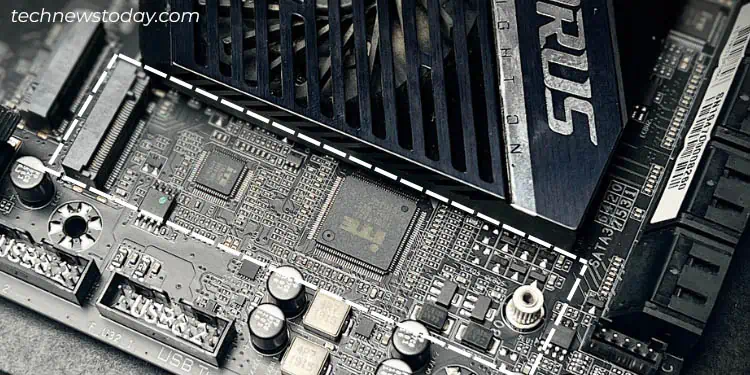
Although most of us still rely on SATA ports for storage drive connection, M.2 SSDs have surely taken the flight in recent years.
They offer relatively faster speed as they utilize the PCIe bus. The processor lanes are not just reserved for x16 graphics cards but also for M.2 slots (uses x4 mode) ensuring high-speed SSDs.
In most models, the final two SATA ports share bandwidth with the M.2 slots. To ensure there’s no conflict, your motherboard will block them.
While in other boards, the PCIe x16 slot will be forced to operate in x8 mode. That’s exactly the case with my ASUS ROG STRIX B450-F GAMING. You can look out for such details on your manual or specs data sheet.
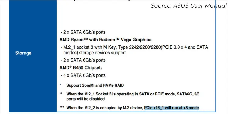
Although there exists M.2 SATA, there’s no difference in speed and performance as these interfaces still use the SATA technology. Most modern boards today embed the NVMe transfer protocol, offering a data transfer rate of up to 20 Gbps.
Their related drives also differ in terms of keys – M in M.2 SATA and B + M in NVMe.
Moving on, the drive installation requires screwing in the relevant screw at one end. Also, I highly advise installing a heatsink (which usually comes installed on the mainboard itself).
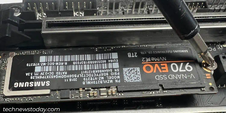
This doesn’t just dissipate heat away from the SSD but even helps improve its performance and extend its lifetime.
The number of M.2 slots can vary depending on the motherboard. Some older ones might only offer one, while others can provide 4 to 5. It also depends on the form factor, as most Mini-ITX boards I know only come with one.
M.2 NVMe drives even come in different lengths – 2242, 2260, and 2280. But there’s no need to panic, as most motherboards in the market support the installation of all three.
Lastly, M.2 slots have not undergone any revisions. The performance improvement solely depends on the PCIe version supported by your motherboard. These include 3.0, 4.0, and 5.0.
CMOS Battery Socket / Holder
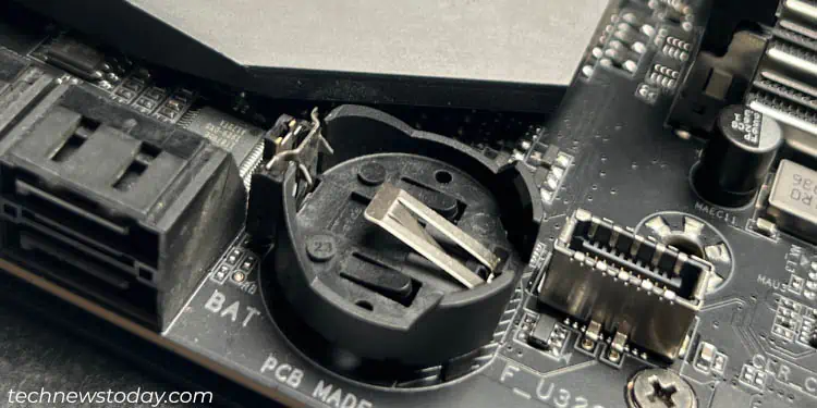
Often overlooked, this socket holds the CMOS battery responsible for powering the BIOS chip. Since all boards come with the battery pre-installed, there’s no need for extra attention.
But you may have wondered what the coin-shaped cell does. Well, it simply ensures your motherboard retains the system configurations at all times, even after the PC is turned off.
You’ll need this when you face any sort of boot-related problems. Simply removing the battery should reset the BIOS parameters. There’s a lock on the socket that you need to push. This should pop it out.
When reseating, make sure the positive side faces upwards. Push the battery in, and you should hear a clicking sound.
Legacy Expansion Slots
As mentioned earlier, PCIe is the standard expansion slot used today. Launched in 2003, it has already superseded almost all of the other interfaces.
But if you own a very old motherboard, I’m pretty sure you’re going to find some other slots instead of PCIe. These may include PCI, PCI-X, ISA, AMR, AGP, and probably more.
To be honest, these slots are of no use today. However, if you want to get a basic knowledge of what they do, the following table should suffice your needs:
| Expansion Slot | Function | Superseded by |
| PCI (Peripheral Component Interconnect) | To attach add-on cards, like sound cards, network adapters, disk controllers, etc. | AGP and PCIe |
| PCI-X (Peripheral Component Interconnect eXtended) | To attach expansion cards | PCIe |
| AGP (Accelerated Graphics Port) | To install video/graphics card | PCIe |
| ISA (Industry Standard Architecture) | To attach peripheral cards | PCI |
| AMR (Audio/Modem Riser) | To attach sound cards, modems, and other expansions cards | ACR and CNR |
| CNR (Communications and Networking Riser) | For the installation of audio, networking, and telephony equipment | Ethernet and Audio ports |
| VESA Local Bus | For attaching video and other peripheral cards | PCI |
| EISA (Extended Industry Standard Architecture) | To attach peripheral cards (superset of ISA) | PCI |
| ACR (Advanced Communications Riser) | To attach sound cards and modems | PCI |

